- 您现在的位置:买卖IC网 > Sheet目录1214 > EVAL-ADE7953EBZ (Analog Devices Inc)BOARD EVAL FOR ADE7953
�� ��
��
��ADE7953�
�OVERCURRENT� AND� OVERVOLTAGE� DETECTION�
�The� ADE7953� provides� an� overcurrent� and� overvoltage� feature�
�that� detects� whether� the� absolute� value� of� the� current� or� voltage�
�waveform� exceeds� a� programmable� threshold.� This� feature� uses�
�the� instantaneous� voltage� and� current� signals.� The� two� registers�
�associated� with� this� feature,� OVLVL� (Address� 0x224� and�
�Address� 0x324)� and� OILVL� (Address� 0x225� and� Address� 0x325),�
�are� used� to� set� the� voltage� and� current� channel� thresholds,� respec-�
�tively.� The� OILVL� threshold� register� determines� the� threshold�
�for� both� the� Current� Channel� A� and� Current� Channel� B� over-�
�current� features.� The� same� threshold� must� therefore� be� used� for�
�both� Current� Channel� A� and� Current� Channel� B.� The� default�
�value� of� the� OVLVL� and� OILVL� registers� is� 0xFFFFFF,� which�
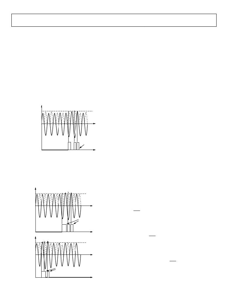
�effectively� disables� the� feature.� Figure� 66� shows� the� operation� of�
�the� overvoltage� detection� feature.�
�V�
�OVLVL�
�Data� Sheet�
�As� shown� in� Figure� 67,� if� an� overcurrent� condition� is� detected�
�on� Current� Channel� A,� the� OIA� bit� (Bit� 13)� of� the� IRQSTATA�
�register� is� set� to� 1.� This� bit� can� be� cleared� by� reading� from� the�
�RSTIRQSTATA� register.� If� an� overcurrent� condition� is� detected�
�on� Current� Channel� B,� the� OIB� bit� (Bit� 13)� of� the� IRQSTATB�
�register� (Address� 0x230� and� Address� 0x330)� is� set� to� 1.� This� bit�
�can� be� cleared� by� reading� from� the� RSTIRQSTATB� register�
�(Address� 0x231� and� Address� 0x331).�
�SETTING� THE� OVLVL� AND� OILVL� REGISTERS�
�The� 24-bit/32-bit� unsigned� OVLVL� and� OILVL� registers� map�
�directly� to� the� VPEAK� (Address� 0x226� and� Address� 0x326)�
�and� IAPEAK� (Address� 0x228� and� Address� 0x328)� registers,�
�respectively� (see� the� Peak� Detection� section).� Note� that� after�
�gain� calibration,� Current� Channel� A� and� Current� Channel� B� are�
�matched� and,� therefore,� the� IAPEAK� and� IBPEAK� registers� are�
�matched� with� common� inputs.� The� settings� of� the� OVLVL� and�
�OILVL� registers� should� be� based� on� the� VPEAK� and� IAPEAK�
�readings� with� full-scale� inputs.�
�To� set� the� OVLVL� register,� the� maximum� voltage� input� should�
�OV� (BIT� 16)� OF�
�IRQSTATA� REGISTER�
�OV� RESET�
�LOW� WHEN�
�RSTIRQSTATA�
�REGISTER�
�IS� READ�
�be� applied� and� a� reading� taken� from� the� RSTVPEAK� register�
�(Address� 0x227� and� Address� 0x327).� This� resets� the� voltage� peak�
�reading.� After� a� wait� period� of� a� few� line� cycles,� the� VPEAK�
�register� (Address� 0x226� and� Address� 0x326)� should� be� read� to�
�Figure� 66.� Overvoltage� Detection�
�As� shown� in� Figure� 66,� if� the� ADE7953� detects� an� overvoltage�
�condition,� the� OV� bit� (Bit� 16)� of� the� IRQSTATA� register�
�(Address� 0x22D� and� Address� 0x32D)� is� set� to� 1.� This� bit� can� be�
�cleared� by� reading� the� RSTIRQSTATA� register� (Address� 0x22E�
�and� Address� 0x32E).� The� overcurrent� detection� feature� works� in�
��IA�
�OILVL�
�OIA� RESET� LOW�
�determine� the� voltage� peak.� This� reading� should� then� be� scaled�
�to� the� amplitude� required� for� overvoltage� detection.� For� example,�
�if� an� overvoltage� threshold� of� 120%� of� the� maximum� voltage� is�
�required,� the� peak� reading� should� be� multiplied� by� 1.2� and� the�
�resulting� value� written� to� the� OVLVL� register.� This� method� ensures�
�that� an� accurate� threshold� is� set� for� each� individual� design.�
�OVERVOLTAGE� AND� OVERCURRENT� INTERRUPTS�
�Three� interrupts� are� associated� with� the� overvoltage� and�
�overcurrent� features.� The� first� interrupt� is� associated� with� the�
�overvoltage� feature;� it� is� enabled� by� setting� the� OV� bit� (Bit� 16)�
�of� the� IRQENA� register� (Address� 0x22C� and� Address� 0x32C).�
�When� this� bit� is� set,� an� overvoltage� condition� causes� the�
�external� IRQ� pin� to� be� pulled� low.�
�A� second� interrupt� is� associated� with� the� overcurrent� detection�
�OIA� (BIT� 13)� OF�
�IRQSTATA�
�REGISTER�
�IB�
�OILVL�
�OIB� (BIT� 13)� OF�
�IRQSTATB�
�OIB� RESET� LOW�
�WHEN� RSTIRQSTATB�
�REGISTER� IS� READ�
�WHEN� RSTIRQSTATA�
�REGISTER� IS� READ�
�feature� on� Current� Channel� A.� This� interrupt� is� enabled� by�
�setting� the� OIA� bit� (Bit� 13)� of� the� IRQENA� register.� When� this�
�bit� is� set,� an� overcurrent� condition� on� Current� Channel� A�
�causes� the� external� IRQ� pin� to� be� pulled� low.�
�The� third� interrupt� is� associated� with� the� overcurrent� detection�
�feature� on� Current� Channel� B.� This� interrupt� is� enabled� by� setting�
�the� OIB� bit� (Bit� 13)� of� the� IRQENB� register� (Address� 0x22F� and�
�Address� 0x32F).� When� this� bit� is� set,� an� overcurrent� condition�
�on� Current� Channel� B� causes� the� IRQ� alternative� output� to� be�
�triggered,� if� the� alternative� output� is� enabled� (see� the� Current�
��REGISTER�
�Figure� 67.� Overcurrent� Detection�
�Rev.� B� |� Page� 48� of� 72�
�发布紧急采购,3分钟左右您将得到回复。
相关PDF资料
EVAL-ADF4002EBZ1
BOARD EVAL FOR ADF4002
EVAL-ADG788EBZ
BOARD EVALUATION FOR ADG788
EVAL-ADM1021AEB
BOARD EVAL FOR ADM1021
EVAL-ADM1023EB
BOARD EVAL FOR ADM1023
EVAL-ADM1031EB
BOARD EVAL FOR ADM1031
EVAL-ADM1062TQEBZ
BOARD EVALUATION FOR ADM1062TQ
EVAL-ADM1075CEBZ
BOARD EVAL FOR ADM1075
EVAL-ADM1087EBZ
BOARD EVALUATION FOR ADM1087
相关代理商/技术参数
EVAL-ADF4001EBZ2
制造商:Analog Devices 功能描述:Evaluation Board For Pll Frequency Synthesizer 制造商:Analog Devices 功能描述:ADF4001 PLL SYNTHESIZER EVAL BOARD
EVAL-ADF4002EB1
制造商:Analog Devices 功能描述:EVAL BOARD - Bulk
EVAL-ADF4002EBZ1
功能描述:BOARD EVAL FOR ADF4002 RoHS:是 类别:编程器,开发系统 >> 评估演示板和套件 系列:- 产品培训模块:Obsolescence Mitigation Program 标准包装:1 系列:- 主要目的:电源管理,电池充电器 嵌入式:否 已用 IC / 零件:MAX8903A 主要属性:1 芯锂离子电池 次要属性:状态 LED 已供物品:板
EVAL-ADF4007EBZ1
功能描述:BOARD EVALUATION FOR ADF4007EB1 RoHS:是 类别:编程器,开发系统 >> 评估演示板和套件 系列:- 标准包装:1 系列:PSoC® 主要目的:电源管理,热管理 嵌入式:- 已用 IC / 零件:- 主要属性:- 次要属性:- 已供物品:板,CD,电源
EVAL-ADF4106EB1
制造商:Analog Devices 功能描述:PLL, Frequency Synthesizer
EVAL-ADF4106EBZ1
功能描述:BOARD EVAL FOR ADF4106 RoHS:是 类别:编程器,开发系统 >> 评估演示板和套件 系列:- 标准包装:1 系列:PSoC® 主要目的:电源管理,热管理 嵌入式:- 已用 IC / 零件:- 主要属性:- 次要属性:- 已供物品:板,CD,电源
EVAL-ADF4108EB1
制造商:AD 制造商全称:Analog Devices 功能描述:PLL Frequency Synthesizer
EVAL-ADF4108EBZ1
制造商:Analog Devices 功能描述:Evaluation Board For ADF4108 制造商:Analog Devices 功能描述:ADF4108 Evaluation Board 制造商:Analog Devices 功能描述:ADF4108, PLL FREQUENCY SYNTHESIZER, EVAL BOARD; Silicon Manufacturer:Analog Devices; Silicon Core Number:ADF4108; Kit Application Type:Clock & Timing; Application Sub Type:PLL Frequency Synthesizer; MCU Supported Families:ADF4108 ;RoHS Compliant: Yes